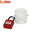
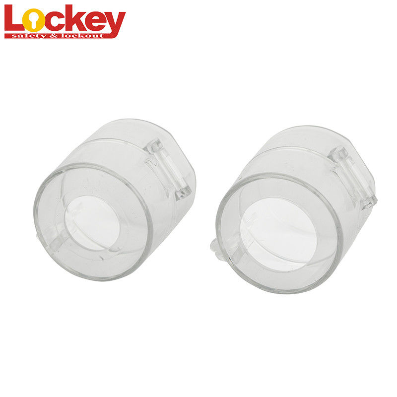
Transparent PC 30mm Electrical Push Button Switch Lockout with inner height 47mm
Part No.: SBL09 SBL10
Emergency Stop Lockout
a) Made from transparent PC
b) Fits on press or screw emergency stop button.
c) Easily used and permanently prevent workers from operating carelessly.
d) Fits both 22.5mm-30mm diameter switches.
| Part no. |
Description |
| SBL09 |
Hole diameter:22.5mm;inner height:47mm |
| SBL10 |
Hole diameter:30min; inner height:47mm |

Develop an energy isolation plan
The EIP-Energy Isolation Plan shall, in accordance with the contents of the operation, JSA analysis results and other process safety information documents of the operation area, set the first and second Isolation points, and attach the Isolation diagrams. The approval of the first and second Isolation points and the approval of the change management shall also be included in the Energy Isolation Plan. The first isolation point is to close or open the valves on the process line in the work area according to the measures formulated by JSA. The electrical isolation shall be physically disconnected in the McC-motor Control Center Control cabinet to ensure that the electric energy is completely removed. For processes or equipment with high risk, secondary isolation points should be set, that is, the blind plate should be installed after the first isolation. The energy quarantine plan is attached To the PtW-Permit To Work To facilitate operators and managers To implement, confirm, and review the correctness and effectiveness of the quarantine.
Perform isolation and validation
Before implementation, determine whether the energy isolation process is for irregular operations, unplanned maintenance operations, operations deviating from safety standards or procedure requirements and other operations requiring operation permit procedures to control risks, and apply for operation permit tickets as required. Energy isolation is implemented in accordance with the energy isolation plan. Note:
(1) The isolation of electrical and radioactive sources shall be operated by qualified professionals. The process personnel and maintenance personnel shall Lockout tagout after the isolation is completed and relevant professionals Lockout Tagout to prevent the risk of accidental release of energy caused by human error operation.
(2) Process operators shall isolate and Lockout Tagout according to the process isolation steps in the energy isolation plan. Maintenance personnel shall Lockout Tagout after confirming the completion of isolation, so as to ensure that materials will not leak due to human error during maintenance and ensure the safety of maintenance personnel.
(3) After the completion of electrical isolation, radiation isolation and process isolation, the maintenance personnel shall apply to the dependency for relevant operation permits related to mechanical isolation. After the approval of the operation permit, the mechanical isolation shall be carried out. The technician shall confirm the mechanical isolation points item by item according to the isolation plan.
When the energy isolation is complete, the residual energy of the isolated part should be released. Electrical isolation. Special attention should be paid to the discharge of capacitors and inductors, as such devices will remain charged for a period of time (about 5 minutes) after the isolation is completed. The isolation of the battery system cannot remove the energy source, and should be electrically treated. In the case of isolation, appropriate precautions should be taken. After the completion of process isolation, it is necessary to drain and replace equipment, pipeline residual pressure and materials.
The effectiveness of the isolation shall be verified before the start of the maintenance work, such as the inching device switch and voltage measurement to confirm the isolation of electrical energy; Confirm the status of the valve, no material discharge from the relief valve, no pressure holding in the system, etc. Maintenance shall not commence until the isolation requirements have been met and if there is a risk that stored energy will re-accumulate to an unacceptable risk level, the isolation shall be continued until the end of the maintenance or until the possibility of such accumulation no longer exists.
 Your message must be between 20-3,000 characters!